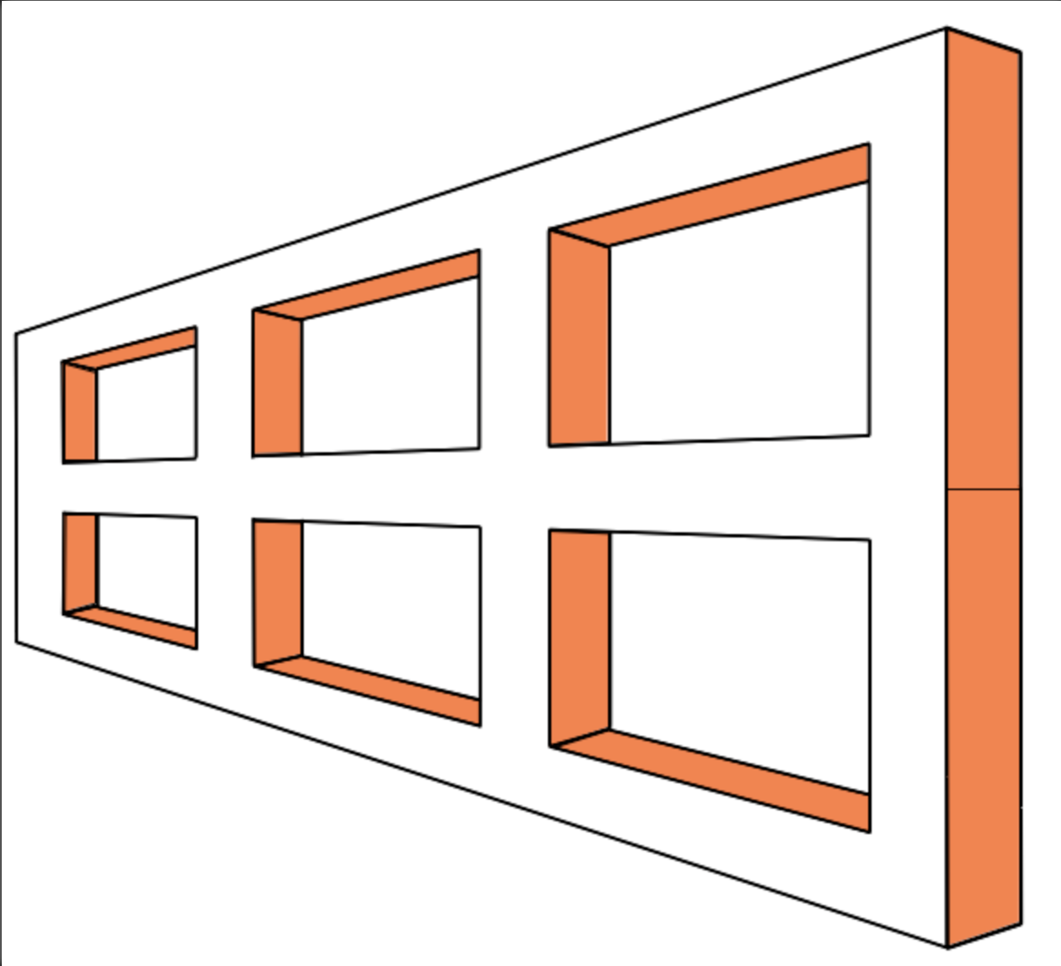
I have always wanted to make something with an Altoids tin. Many creations can be on the internet, mostly using the tin as a container for a fixed display. My original idea had been to use it as the case for a tiny orrery. That comes with a lot of complexity. For some reason I was exploring various optical illusions and saw one called the Ames Trapezoid. A trapezoid cut to look like a window frame seen with a lot of perspective is slowly rotated. The "window" appears to turn back and forth as opposed to rotating through a full 360°. Wikipedia, of course, covers the Ames Trapezoid.
The dimensions are set by the Altoids tin, 3/4" X 2 3/16" X 3 5/8". The corner radius is approximately 7/16". The worm and wheel need to fit within 2 3/6" if the worm is to be driven by a handle emerging from the side of the box. A larger wheel can be used if the handle emerges from the front side of the box.
The basic design will consist of a minimal number of parts. The worm and wheel will be sandwiched between two 1/8" thick metal plates. Two bearings will span the gap between the plates and hold the worm in place. A third bearing will seat the inserted handle. The handle and the window will be stored on the top plate and attached prior to a demonstration. The wheel will probably require spacers above and below to correctly position it and to hold it in position.
Two posts might be needed to support the two corners opposite the worm's location. Locating it on the backside puts the handle in the back corner. Moving the handle farther away from the corner means the wheel diameter has to be reduced. Locating the worm parallel to one side and inserting the handle from the front will minimize impact on the wheel diameter.
Most of the parts will be made from brass: worm, wheel, axle, spacers, top and bottom plates, columns, bearings and handle. Cutting the trapezoid will be a challenge. Aluminum would be nice, but wood might be easier to pull off. This part could be assembled from parts and glued. Angles are going to be a challenge. The handle will be simple screwdriver to insert in the end of the worm shaft. Unlike the orrery this connection will be made within a bearing, minimizing play.
The gear ratio of the worm drive is the size of the wheel to 1, or one turn of the worm advances the wheel by one tooth. A twenty tooth wheel would require 20 turns of the worm for one complete rotation. That sounds like too many, though we want the trapezoid to turn slowly. Somewhere between 12 and 16 teeth should be ideal. This will make for a reasonably small wheel using the gear cutters I possess. The formula for the OD of a gear is (# of teeth + 2) / pitch. A 12 tooth gear of 30 pitch will be 0.467" in diameter, a 16 tooth gear, 0.60". This plus the diameter of the worm means the two can easily fit in either orientation.
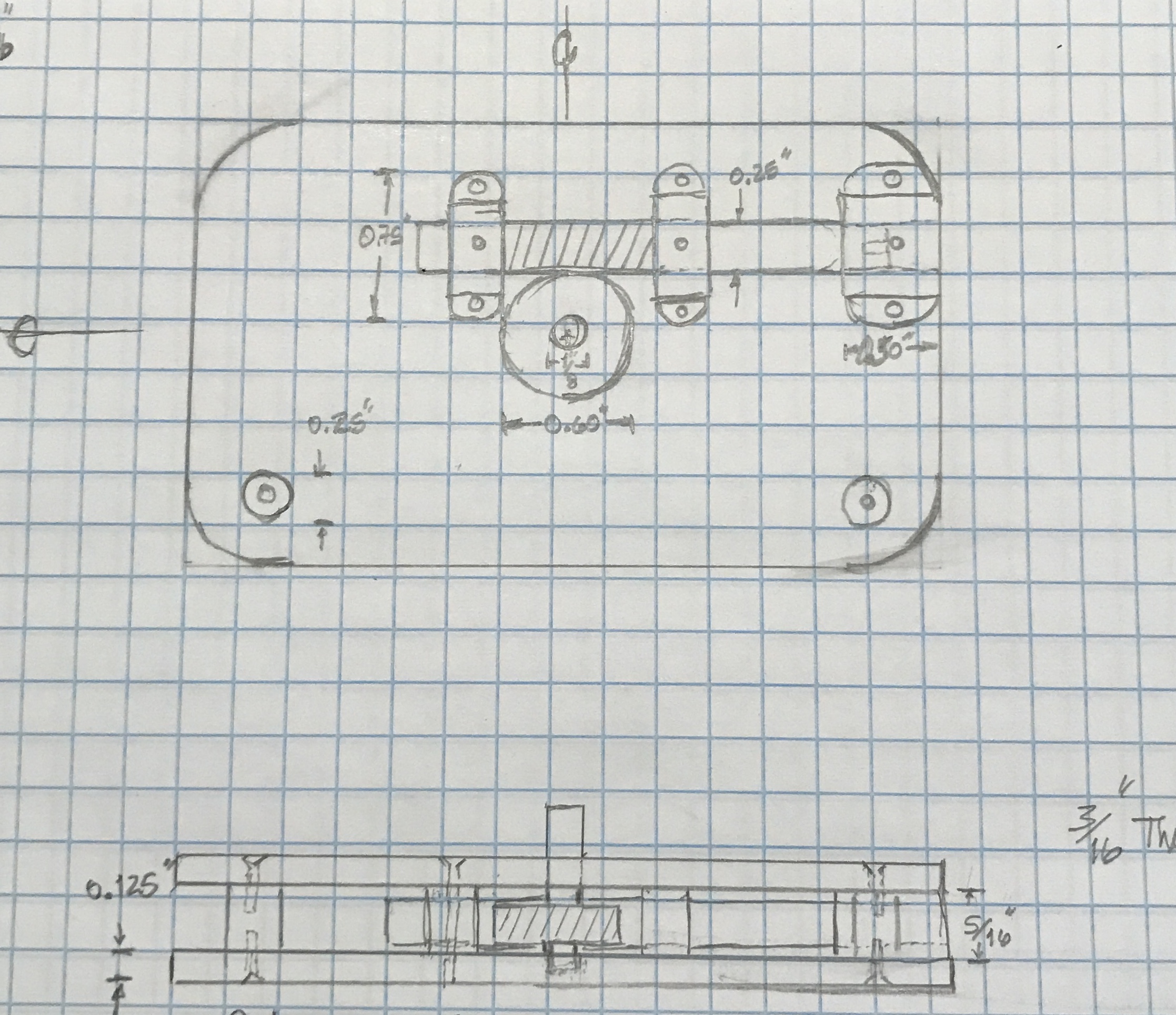
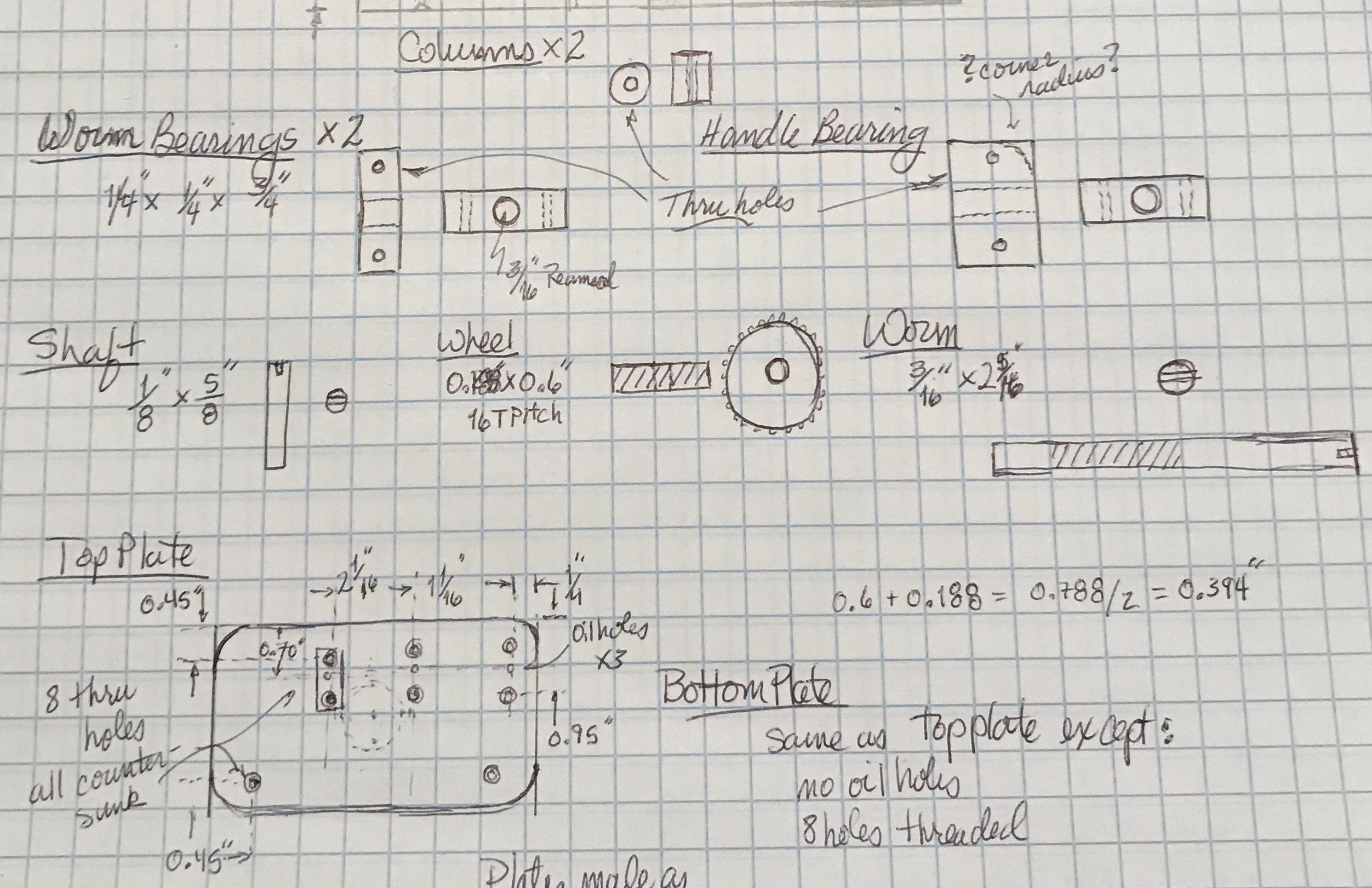
Above are the MAD plans for the overall mechanism and for the parts of the device with the exception of the handle and the rotating window. The worm and the wheel are sandwiched between two 1/8" thick plates. The wheel is supported by the shaft whose presence is not shown in the top plate plan above. The shaft is centered on the plates. The top plate has a through hole for the shaft, whereas the bottom plate is only bored 1/16" deep for the shaft. The two plates will be made while clamped together and then separated prior to opening up the holes in the top plate. The only items not yet planned are the screws to be used, the handle design, and the window design. The plates are held apart by the three bearing blocks and the two columns.
The screw stash has 2-56 SHCS's. The clearance hole for these screws should be 0.104". The heads are 0.136" OD and 0.088" high. These should work well with the dimensions of the different parts. The black will be a nice contrast with all of the brass parts. The screws are 3/4" long and can be cut to fit. There is no brass or aluminum 1/8" plate in the stash, so some will be purchased. Purchased 1/8" X 2 1/2" brass bar from Online Metals. Their price was about 20% cheaper than Speedy Metals even before the 20% discount they offered. Unfortunately, I don't need any other metal. The brass bar arrived this morning. Can't wait to get started, but a few other projects for Rhea have taken priority.
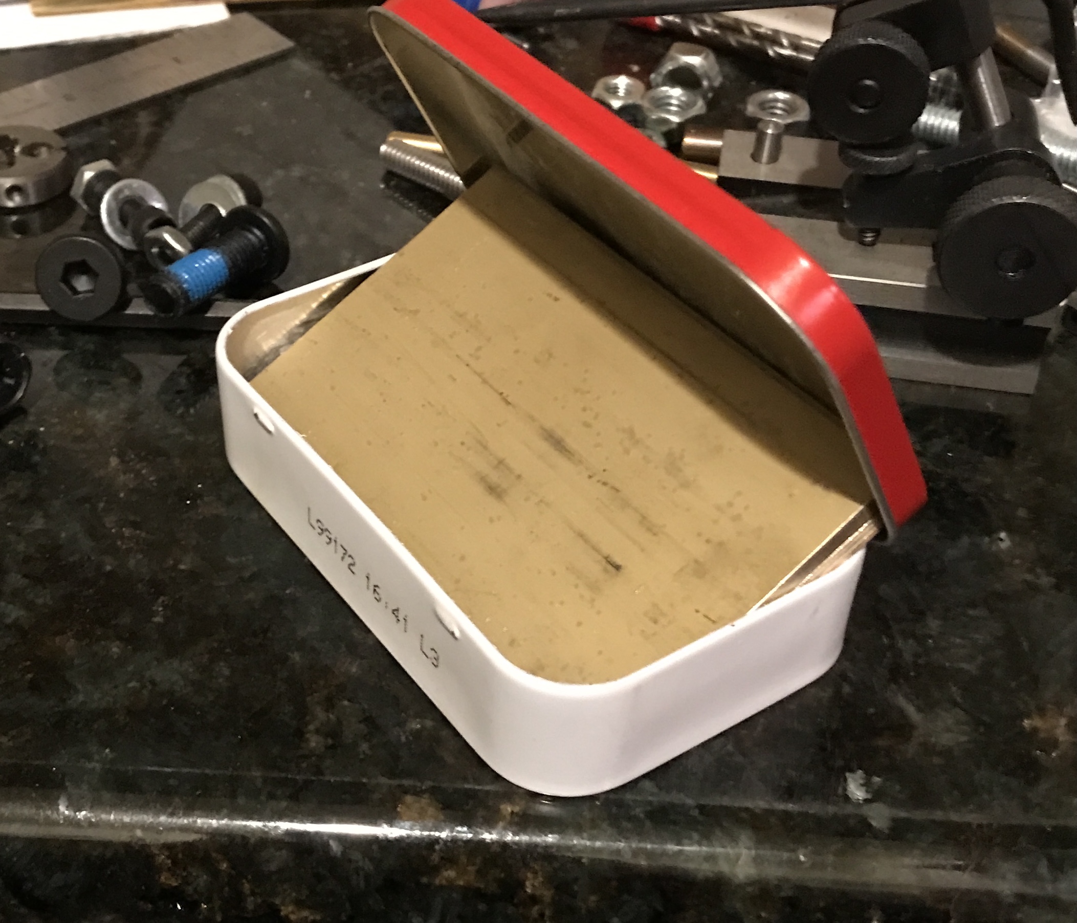
The brass was cut to size this morning. Two rectangles were marked at 3 9/16". These two lengths were cut free from the bar with the bandsaw. Both parts were marked at 2 3/16" and cut to size again with the bandsaw. The newly cut edges were deburred. As can be seen in the photo below both parts fit nicely in the Altoids box. They fit in the other direction as well. A little filing was done to smooth the edge cut by the supplier.
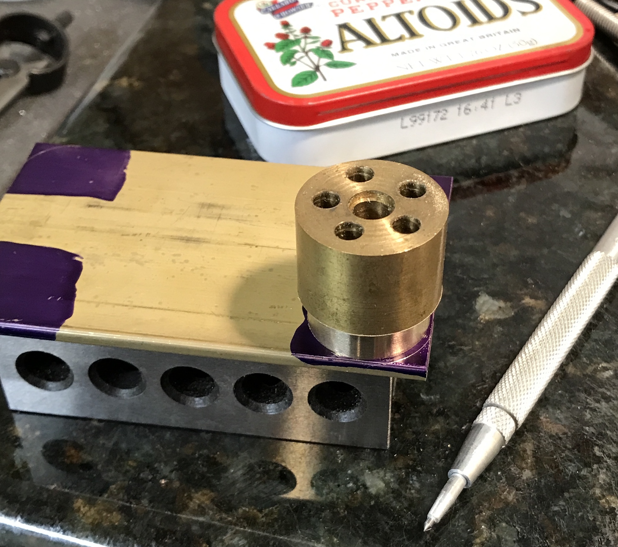
The corners needed to be marked for rounding. I couldn't find a 7/8" piece of round anything, so one was quickly made on the lathe from an old miss-drilled cylinder. This was placed on the brass and aligned flush against two edges before marking the arcs on eight corners. The photo shows this work in progress.
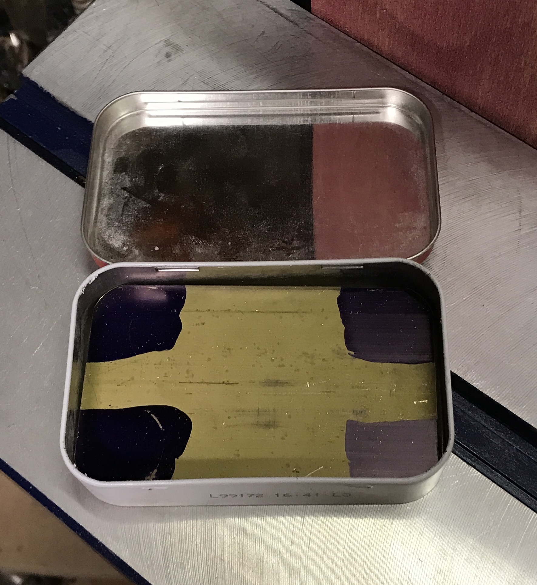
The corners were rounded to the marked lines with the belt sander. The belt was first raised to the vertical position and the table installed. It was quick work to round the corners. After two adjacent corners were finished, the edge was tested in the box. The photo below shows the two plates sitting in the box.
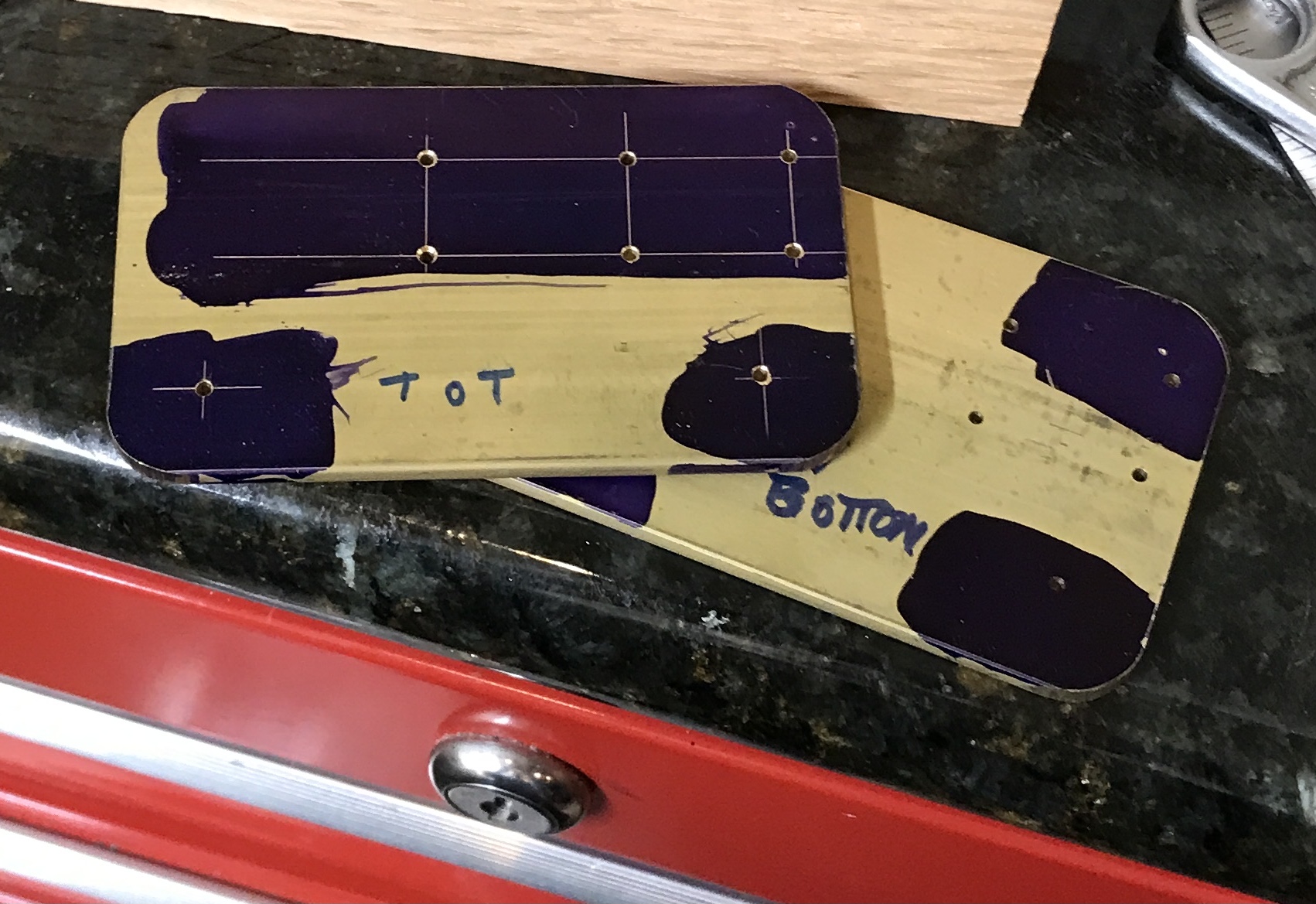
The rest of the work will proceed as follows. The top and bottom plate will be marked as such. A corner (two adjacent sides) for each will be chosen and marked as a reference. The top and bottom of each plate will be marked. The two plates will be clamped together for drilling with the tap drill. The top plate's holes will then be opened up to through holes and countersunk for the screw heads. The bearings will be made and screwed in place for final reaming to size (3/16"?). After making the worm and wheel the hole for the worm's axle will be marked and drilled on the plates. Columns and a handle complete most of the machining. The window frame will be first modeled in cardboard to determine the best angles.
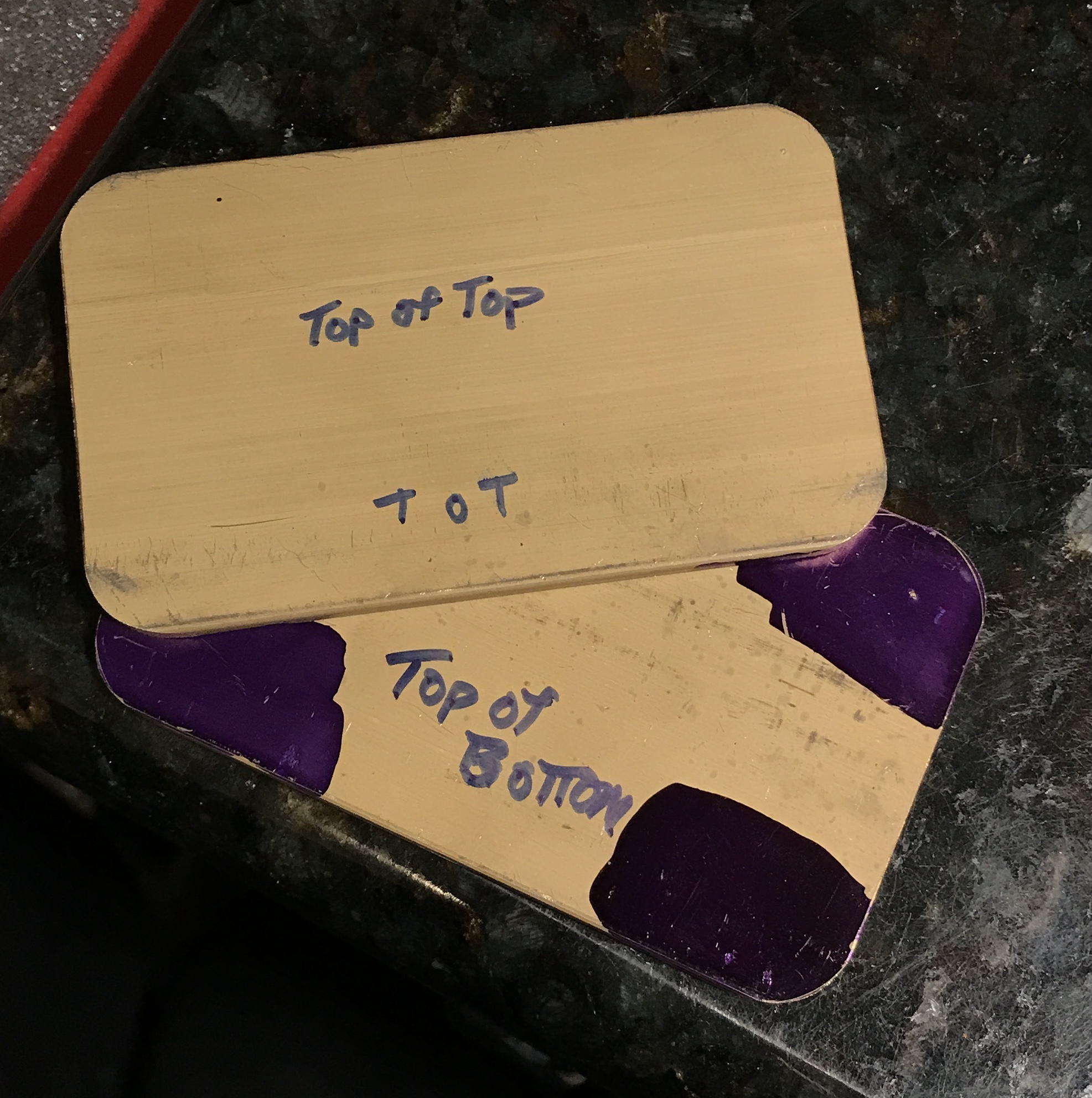
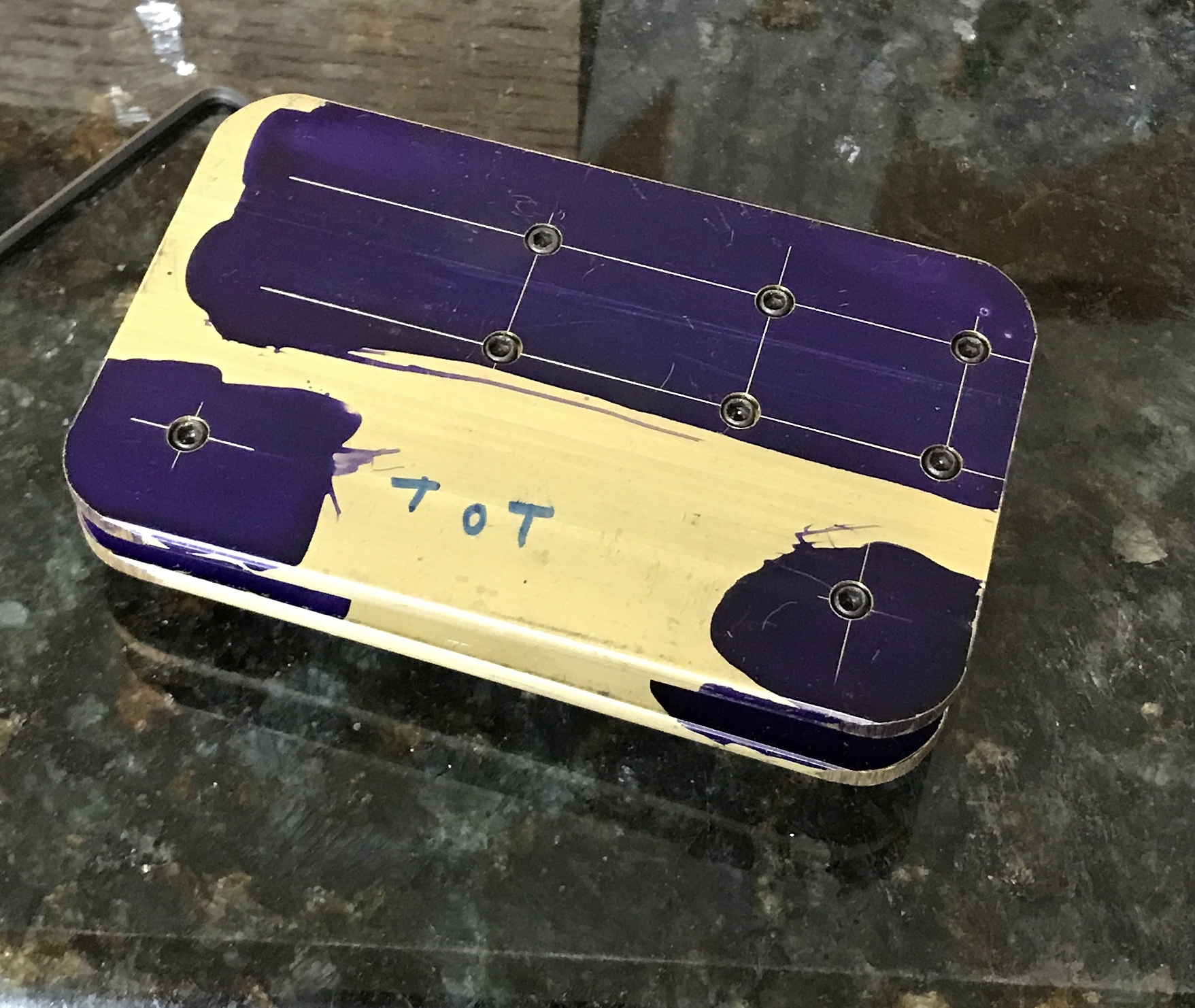
The top, bottom and their tops were marked. The "best" corner was selected and punched. The top plate was marked for the six bearing holes and the two column holes. The plates were then clamped together with two machinists clamps. The clamps were held in the vise on the mill with the plates set up on 1/8" scrap. The eight holes were center drilled and drilled with a #50 drill using the sensitive drilling jig. The drilling was difficult probably due to a dull drill. After the drilling was complete the holes in the bottom plate were tapped 2-56 and chamfered with a #32 drill.
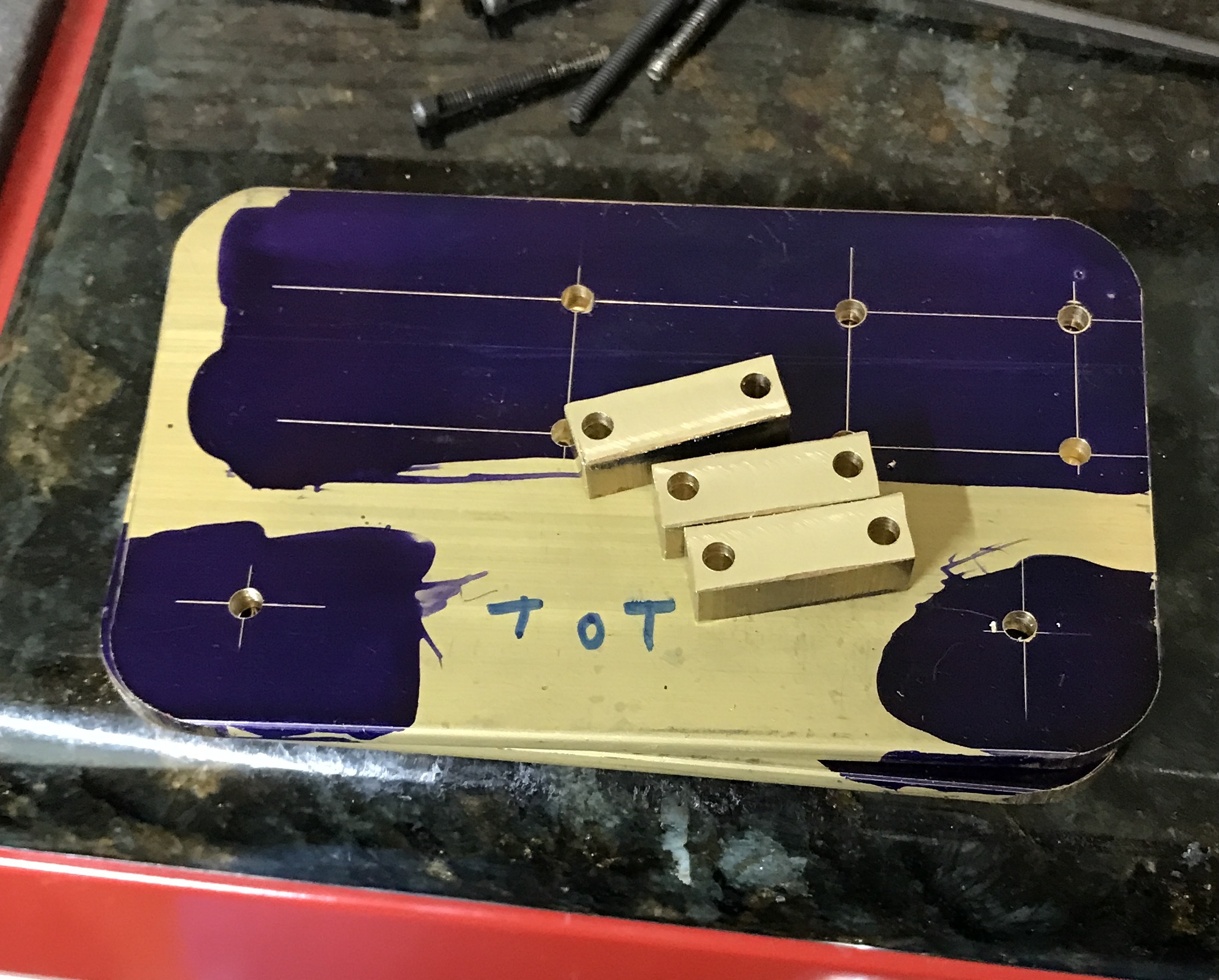
The bearings were made next. A 1/4" X 3/4" bar of brass had three 5/16" lengths cut off with a hack saw. The cut sides of two were lightly filed and the two lengths of brass were held in the vise on the mill. A 5/16" end mill was used to flatten one of the cut sides. The third was treated similarly. The three parts were then set on their end mill cut sides on parallels in the vise. A strip of paper was used to hold all adequately for milling to 0.250". All corners were deburred. The three bearing blocks were returned to the vise. After locating the fixed jaw of the vise the table was moved 3/32". The table was moved so the spindle was centered on a bearing and 3/32" from the end. A hole was center drilled and then drilled with a #37 drill. The other two bearings also had the one hole drilled.
At this point the eight holes in the top plate were opened with the #37 drill. The bearings and their locations were labeled. Screws were run through the top plate and the bearing and a nut. The bearing was aligned parallel with the reference edge and the second hole in each bearing was transfered with a punch. The three transfered holes were center drilled and drilled with the #37 drill. The first photo below shows the three bearings at this point. The second photo shows the test fit installation between the two plates.
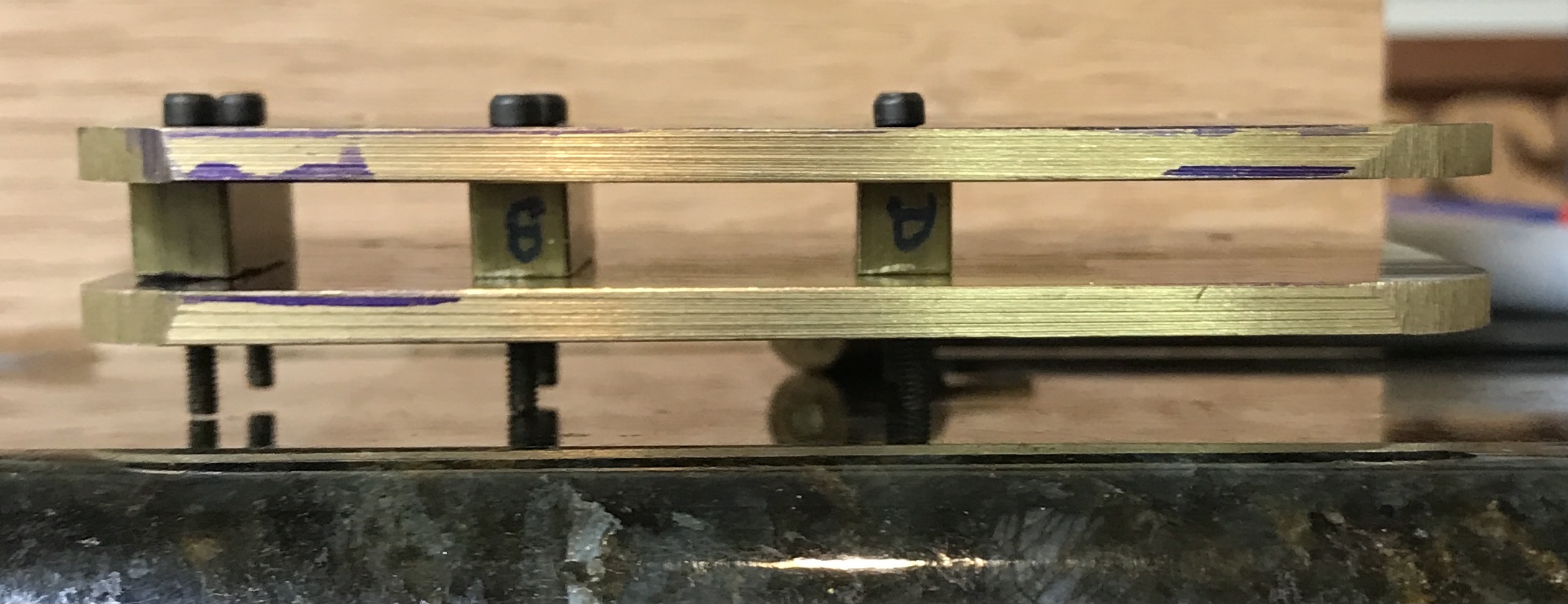
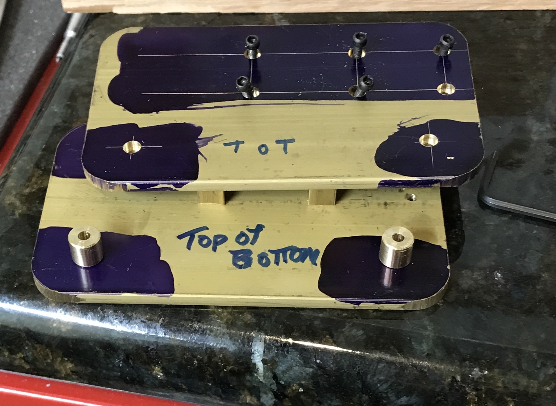
The columns were made from a misformed 3/8" brass screw. The threads were removed. No attempt was made to reduce the brass to 0.25". The brass rod was center drilled and drilled 0.104" for 1/2". The end was chamfered and a 0.250" length was parted off. A second length was parted off as well producing the two columns. The first picture shows the two columns sitting on the bottom plate. The second photo shows them in place. The holes in the top plate were countersunk 0.090" deep with a 5/32" end mill. The third photo shows the seven parts assembled at this stage.
The next step is drilling and reaming the hole for the worm shaft. The entire process will be done with the bearing blocks assembled between the plates. The bearings will be punch marked to indicate both position and orientation. After drilling an 11/64" hole through all three bearings the oil holes will be drilled. Then the bearings will be reamed in place. The worm shaft will be used to realign the bearings after disassembly.
An issue has come to mind. Reading over the third construction of the worm for the orrery, indicates that the spiral is cut 0.072" deep. On a worm that is 3/16" diameter this leaves less than 1/16" uncut in the center of the worm! I will switch to a 1/4" worm. The non-worm parts of the shaft will remain 3/16". In order to accomodate the larger worm, slots will need to be cut in the top and bottom plates. A feature not a bug!
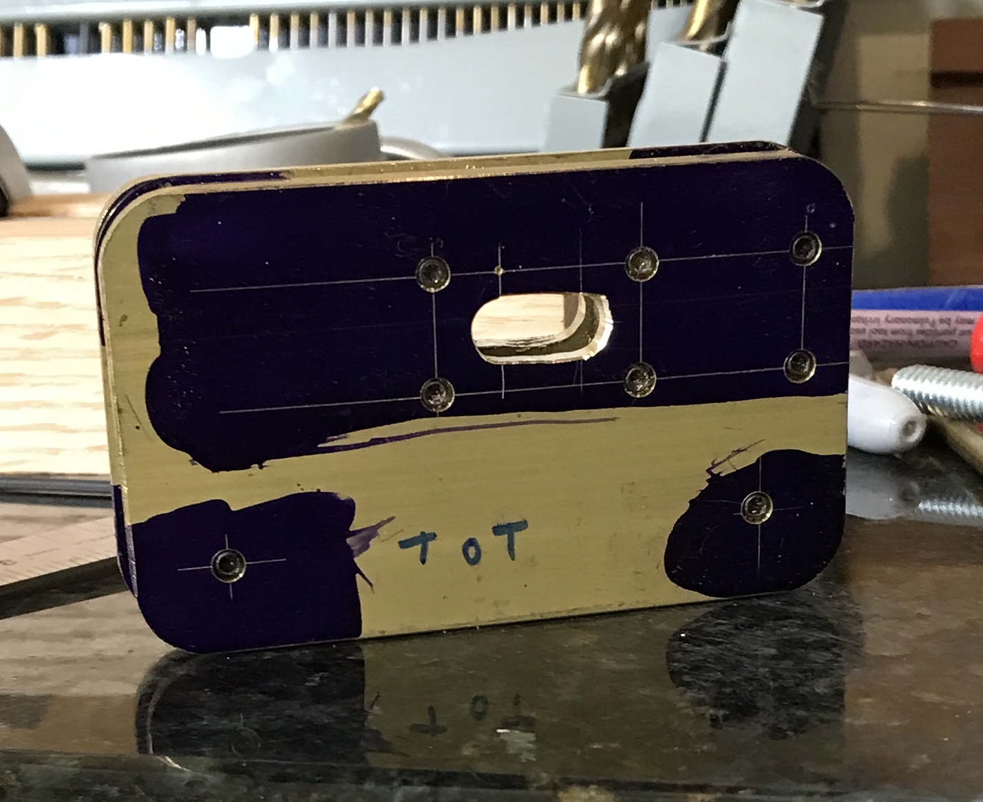
The assembled top and bottom were marked on the top for two holes. These holes were marked 1/4" + 0.05" in from the lines marking the centers of the two worm bearings. They were centered between the perpendicular lines. The holes were centered drilled, drilled with a #19 drill and then opened to 1/4". The top and bottom were drilled together, while holding the unit on top of a the milling vise using two strap clamps. A slot was opened between the two holes with a 1/4" end mill in the top and then the bottom. The slot was cleaned up with a deburring tool. The photo shows the not quite symmetrical slot. The y-axis drifted during the milling.
The screws were cut to length. The unit was disassembled and six nuts were placed on a screw. The screw was cut off with a hack saw at the extent of the nuts, while holding it in the vise. The end was deburred with a file and the nuts removed, placed on the next screw and the process was repeated for all eight screws. The unit was reassembled showing the screw ends, as desired, were all slightly buried in the bottom plate.
The plan for drilling and reaming the bearings is as follows. The center of the "C" bearing, the handle bearing, will be marked. Bearing "C" will be made parallel to the end of the top plate and tightened in place. An adjustable parallel will be used to align the "B" bearing with the "C" bearing. The "B" bearing will be tightened and again an adjustable parallel will be used to align the "A" bearing with the "B" bearing before tightening the "A" bearing in position. With all of the bearings aligned and parallel with an edge the bearings will be drilled and reamed, while holding the assembled unit offset in the four jaw chuck on the South Bend lathe.
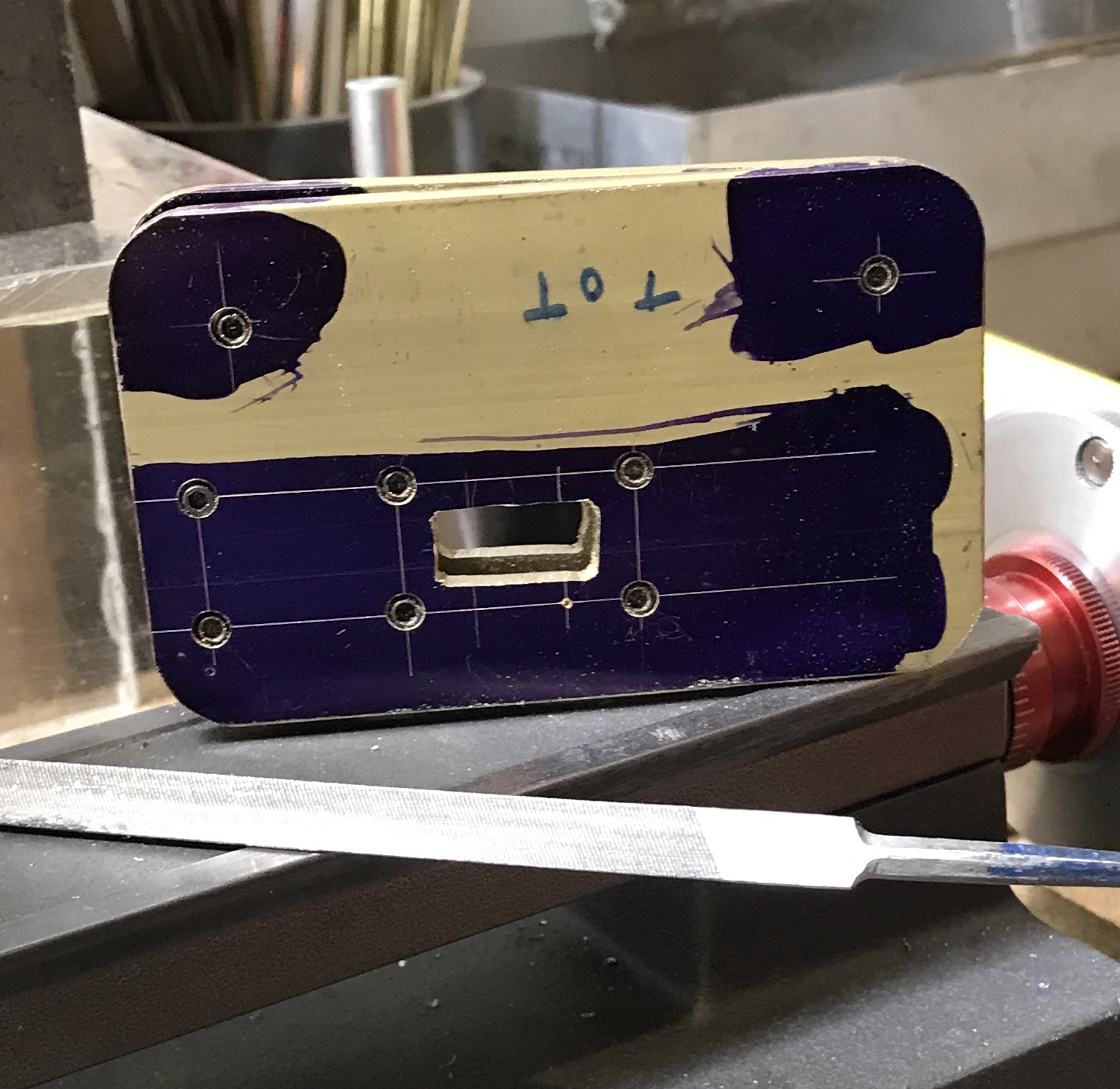
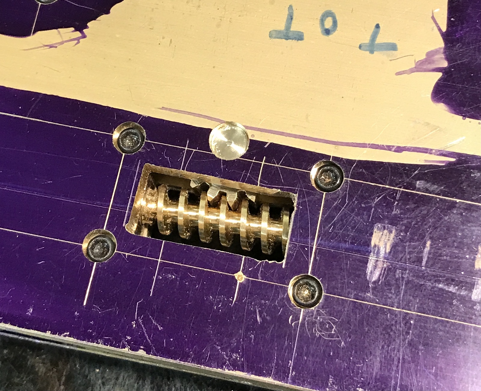
The worm will be made this morning. Rhea is at Pilates this morning, so any noise will not be a problem. Before she left the opening in the top and bottom plates were filed square with a triangular file as shown in the photo below.
A 2.5" length of 1/4" brass round was cut off with a hacksaw. One end was faced in the lathe and center drilled. This end was reduced to 0.187" for 1". A mark was made 11/16" from this reduced portion. The part was flipped in the chuck and the end was faced and center drilled. This end was then reduced to 0.187" up to the marked spot. Clearance was cut for the thread ends, but not enough.
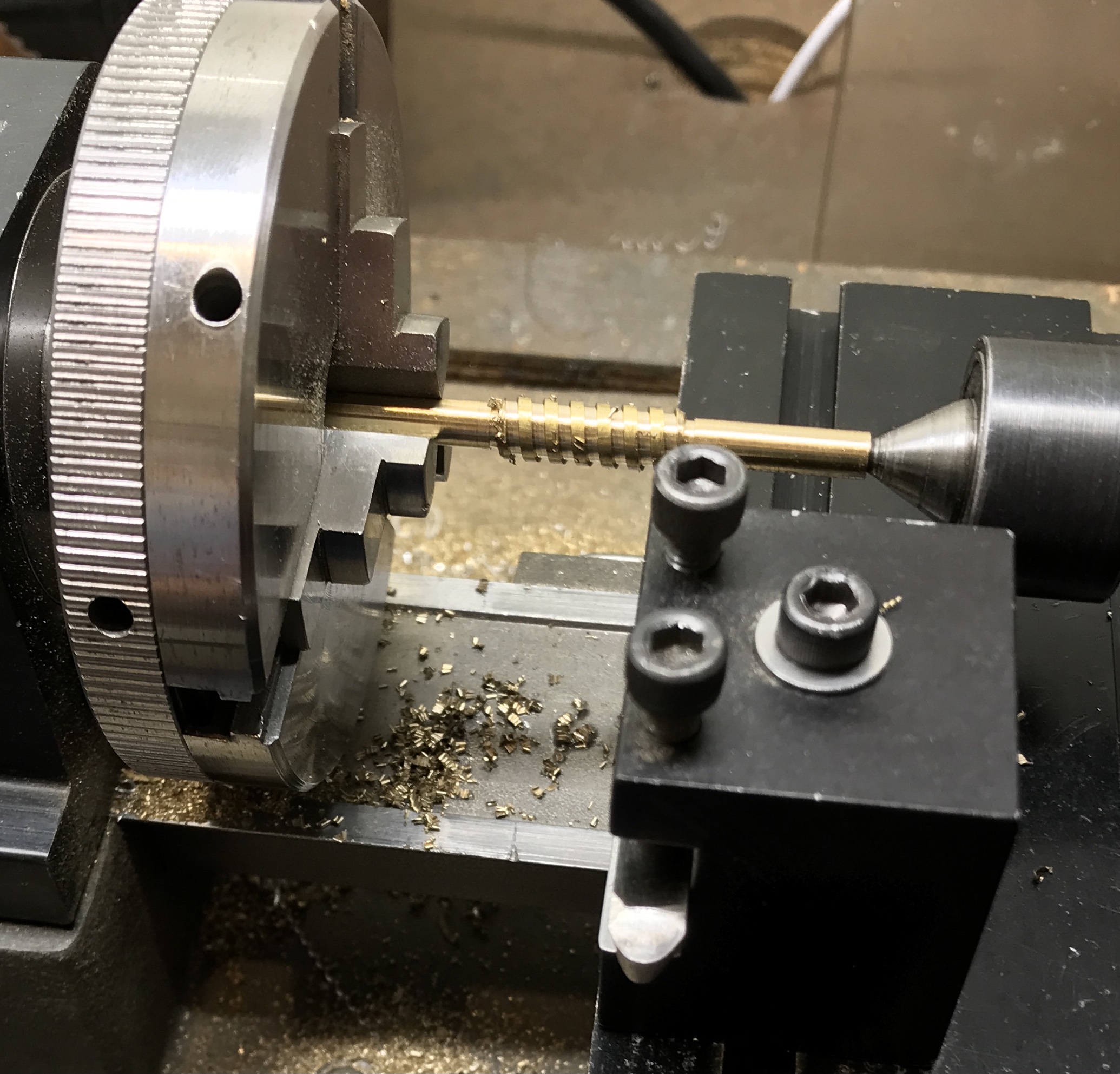
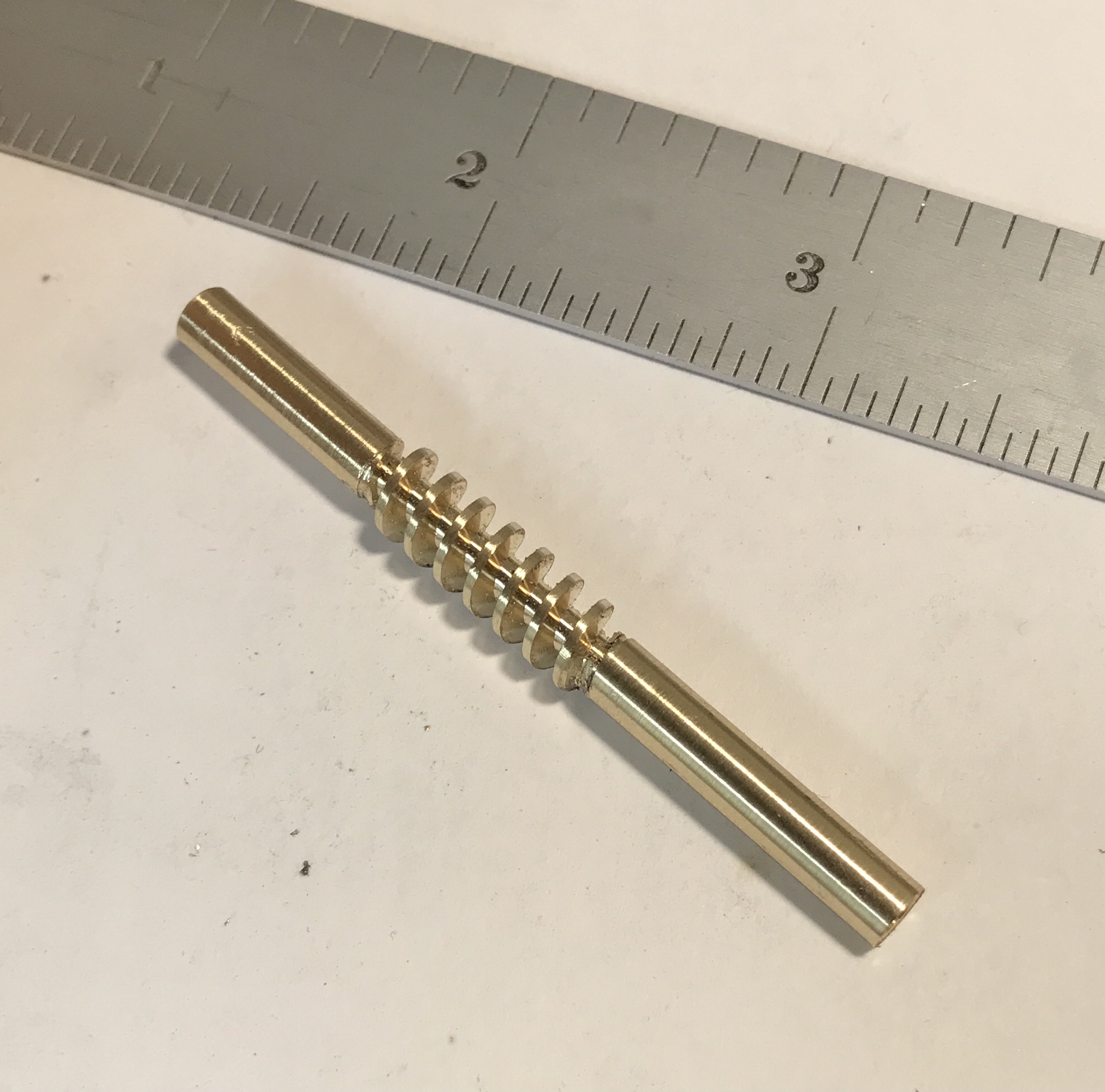
The thread pitch on the worm needs to match the pitch on the wheel. This wheel will be cut with a 30 DP cutter, so the pitch is π/30 = 0.1047" or 9.55 teeth per inch. To cut a 9.5 pitch thread on the Sherline the 19 pitch gear setup is utilized with a 50 tooth gear replacing the usual 100 tooth "B" gear. In this setup a spacer is used between the spindle gear and the handle. The lathe was set up for gear cutting with these considerations in mind. The thread was cut to a depth of 0.072", the majority in steps of 0.001". The last few passes were recut after each depth change. The first photo shows the worm being cut. After returning the lathe to its powered state the threads were touched up with crocus cloth. The second photo shows the completed worm.
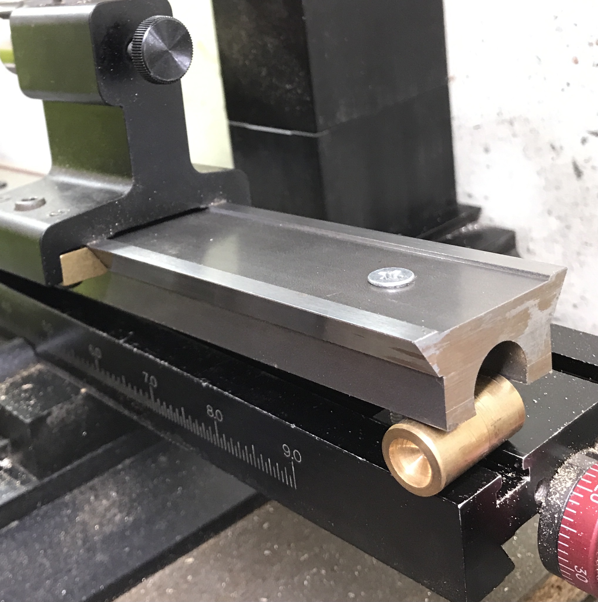
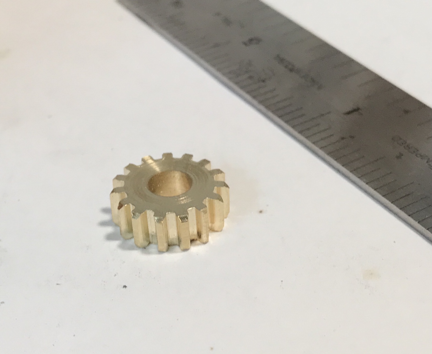
The wheel will be made this morning as Rhea is giving Jerry dancing lessons in the garage. Gear cutting can be rather noisy. A fifteen tooth wheel has been selected. The requisite OD is 0.567". A scrap of brass hex stock was found with a 0.198" central hole. The stock was reduced by facing to 0.188". An old mandrel was modified to fit this hole and a brass washer was located to match the fit. The hex stock is seen in the photo below held on the mandrel ready for machining to diameter.
The Spur Gears calculator says a number 7 gear cutter is needed. This cutter is 0.215" thick and half of the OD is 0.283", so the cutter was touched off on the top of the blank and lowered 0.498". After completing the gear I realized two things were done incorrectly! This was a practice run. The cutter should have been lowered 0.390" and the gear was not set at the appropriate angle, 3.8°. For ease of cutting the gear also needs to be 1" from the chuck to allow room to complete the cut and avoid running the cutter into the chuck.
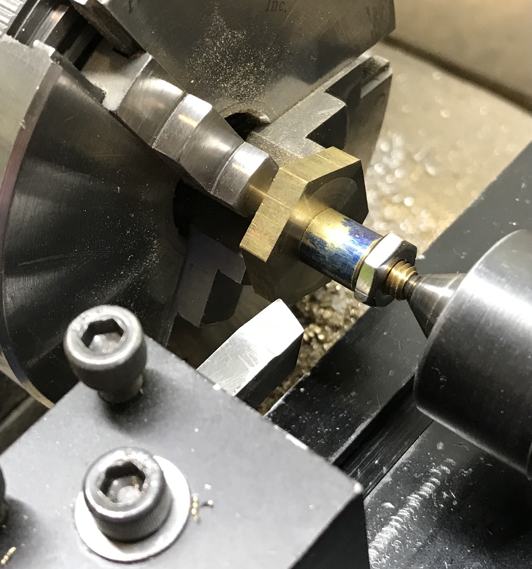
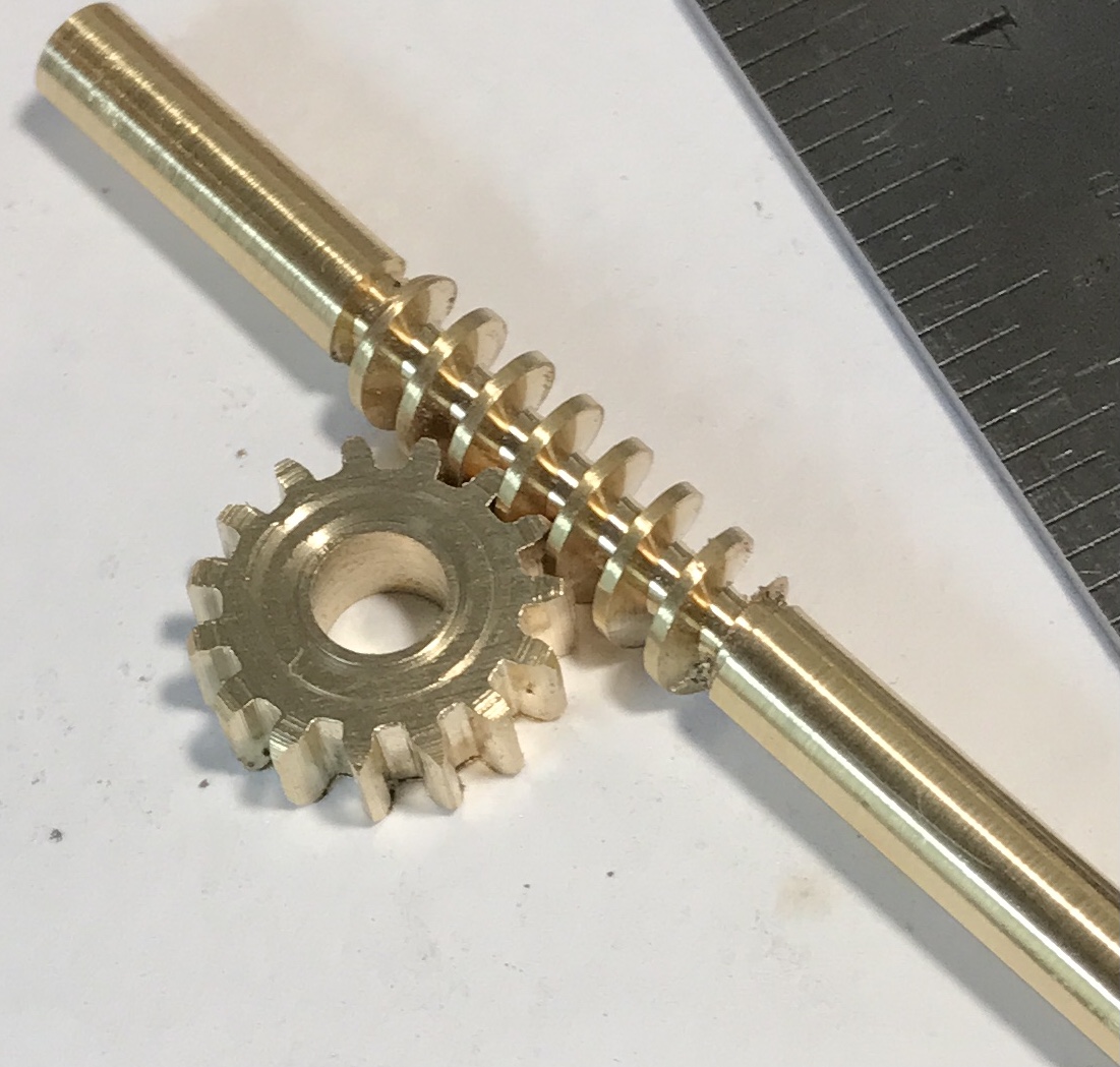
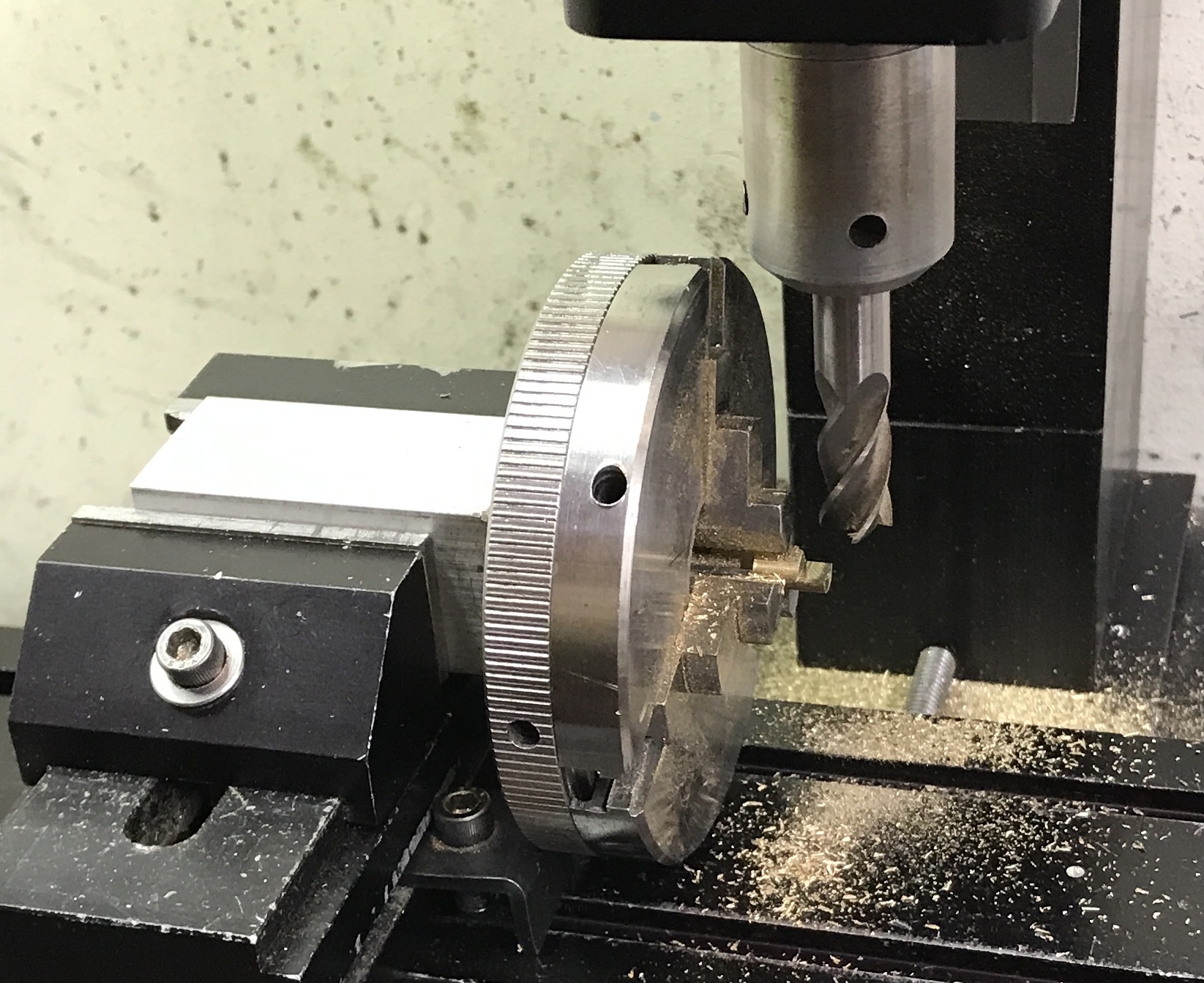
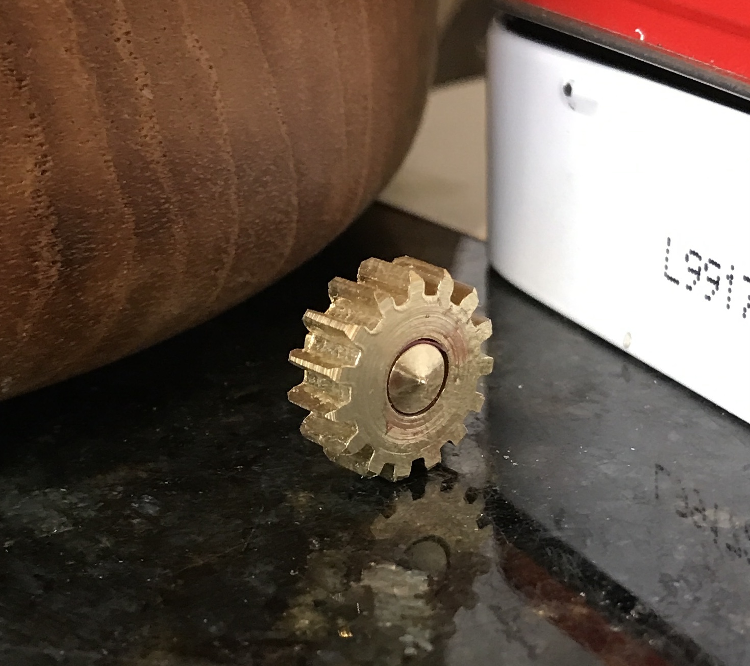
A new blank was made from 3/4" brass round. It was spaced appropriately prior to machining it to size. The two corners were heavily beveled with a file. The chuck with blank was transferred to the dividing head. The platform supporting the head was raised at one end by 0.5". This was measured to be 3.9°, close enough to 3.8°. This is seen in the first photo below. Two long 10-32 screws were used to anchor it to the table. (This is a precarious way to accomplish this. Ideally, holes would have been drilled and tapped in the angle table to fit. The cutter was touched off on the top of the blank and lowered 0.390". The Libre Office spreadsheet was used to calculate the offsets based on the measured starting length of the rack. Ninety minutes later the gear was complete. It was filed on both sides to remove burrs. It is seen in the second photo below, and shown meshed with the worm in the third.
An attempt was made to cut the slot on the end of the shaft. The saw was set on the top of the shaft and dropped half of the width of the shaft (0.099") and half of the blade width (0.029"). Depth of cut was 0.005". At one point the shaft moved and the cutting was halted. It is difficult to hold the shaft in the machine vise. Another method must be found. Vise and hacksaw may be the way to go.
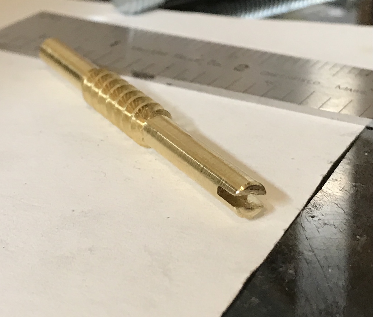
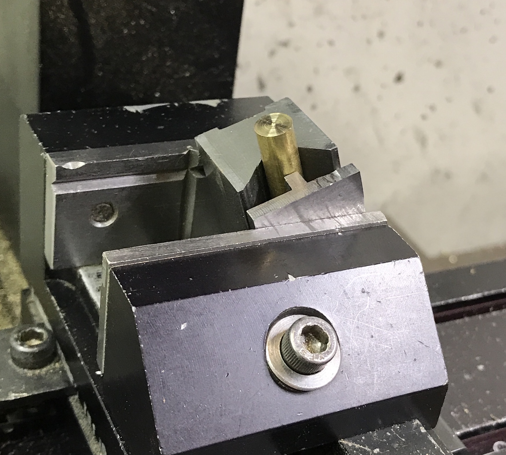
After recovering from demonstrating crystal growing for two third grade classes, I am back on the project. The buggered up end of the worm was faced in the lathe. The worm was then held in the basement vise and a slot was cut with a hacksaw centered on the long end of the worm. This slot was opened with a needle file to 0.046" as measured with thickness gauges. The slot is about 1/8" deep as seen in the photo below.
The worm needs to be installed so the wheel center can be located. The axle for the wheel will be a pointed rod of brass. The axle will have a slot in one end and the other end will be pointed. This pointed end will sit in a small drilled hole in the bottom plate. The wheel was located in relation to the worm and a center punch was used to mark the center of the wheel's hole on the bottom plate. The mark was drilled with a #50 drill. The two plates were clamped together aligning the two reference edges. The hole was continued through the top plate. The top plate was removed from the clamps, drilled and reamed 3/16".
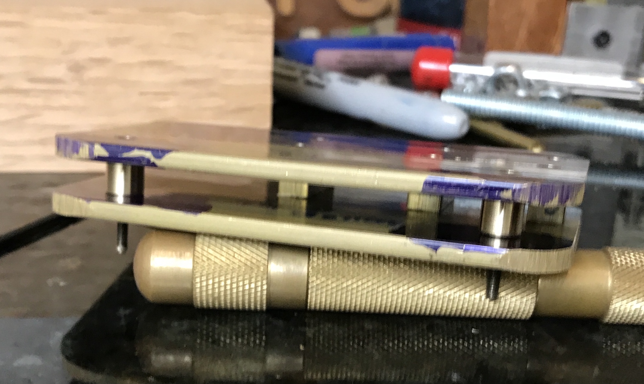
A pointed (40° included angle) shaft was made and then I realized that most of the axle in the shaft was removed!. A file was used to make a much larger angle on the end and the shaft was cut off at 0.32". The first photo below shows the shaft and the second the device assembled. The end of a small file was used to easily turn the worm, turning the wheel! Eventually the shaft will be glued to the wheel.
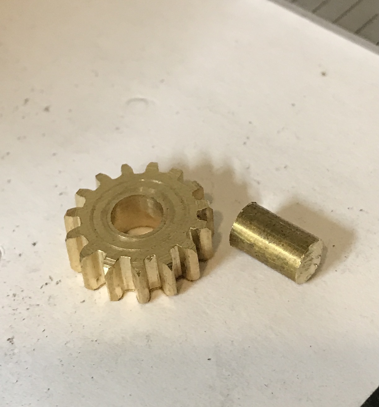
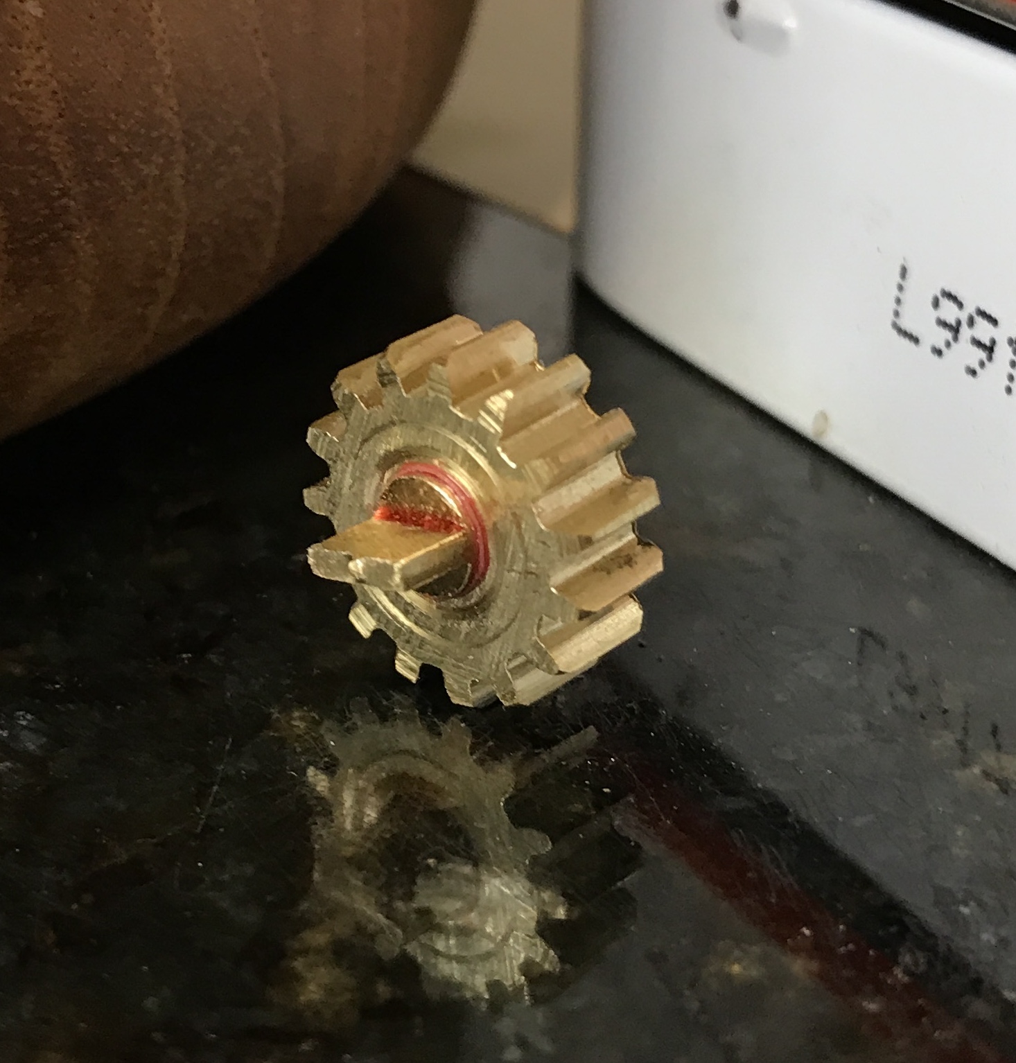
I didn't like the looks of the axle made above so it was remade. A piece of 3/16" round stock was held in the chuck and the headstock was turned 15°. It was faced to give a 150° point. After parting off at 3/8" this part was turned end for end in the chuck. The chuck was removed from the lathe and attached to the 4-sided indexing block. This was held in the vise on the mill. The chuck was pressed against a clamp holding the vise to the table as a stop. The top and front face were located and the head was lowered 0.071". The end of the axle was cut 0.140" in 0.010" increments. The block was turned over in the vise and the operation was repeated. An additional 0.018" was removed in order to fit in the worm shaft. Might as well keep things consistent. The axle was cleaned up a bit and glued into the wheel with the point just protruding. The fit was poor (must have removed too much material cleaning up the axle) so a strip of paper was used in the joint.
The handle was made next. A 1/4" X 1/2" rectangle was marked out on a scrap of 1/16" brass sheet. Centers for two holes were marked. The attachment to the worm shaft will be 3/16" in diameter, while the handle at this end will be 1/8". Holes were drilled in the strap and the part was cut free of the scrap with the hacksaw. It was deburred and cleaned up with a file and sandpaper. The corners were rounded. A part similar to the axle was made in the same fashion, but without the point on one end. A 1/2" long handle was made by marking out a few places on a 3/16" round rod for cutting. The rod began with a rounded end as it was an extra part from the Monkey Puzzle. 1/2" from the end the parting tool was used to make a 1/32" deep groove. This groove was extended to the right for ~1/8". the groove was gradually made less deep over the next 1/8". After a little work with a file and the part was parted off. These parts are documented in the three photos below.
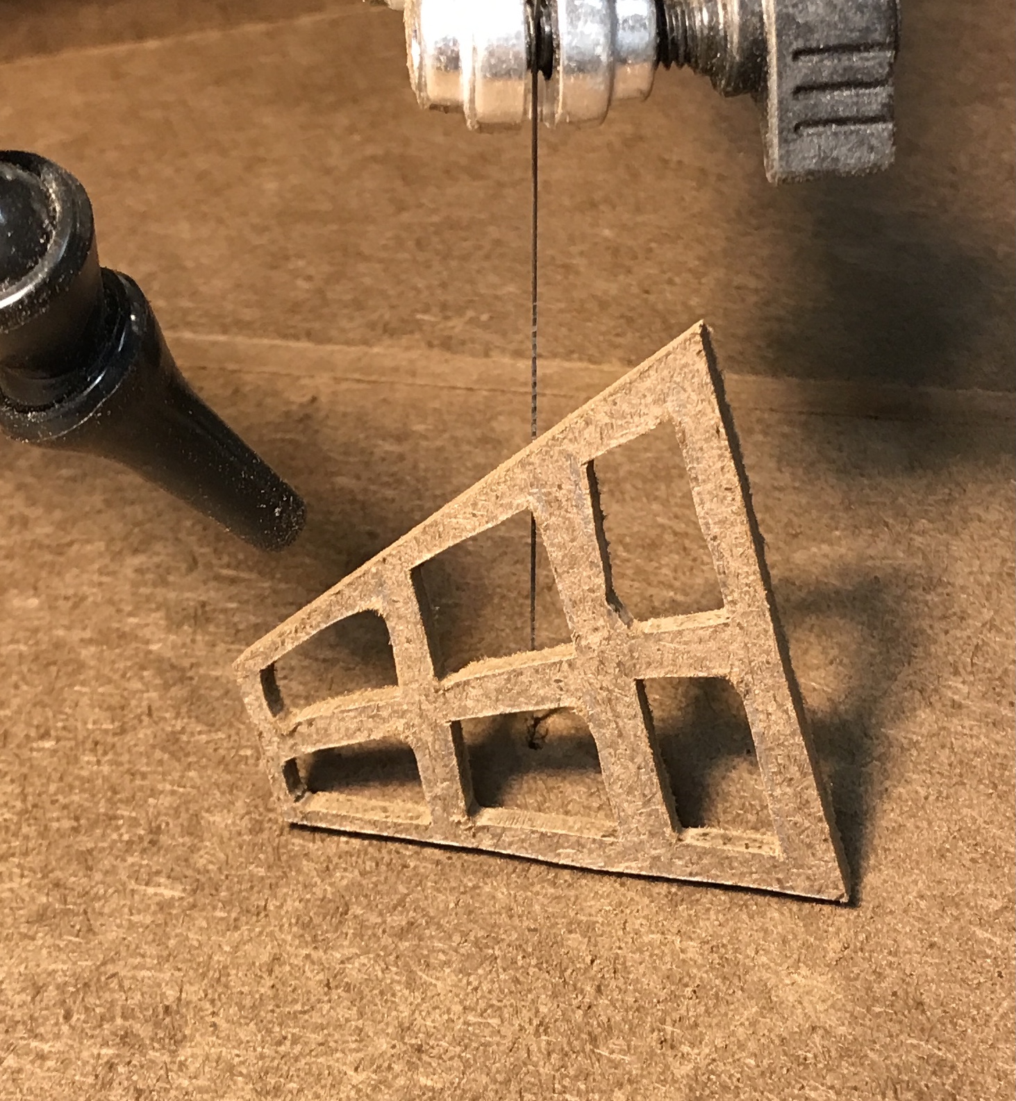
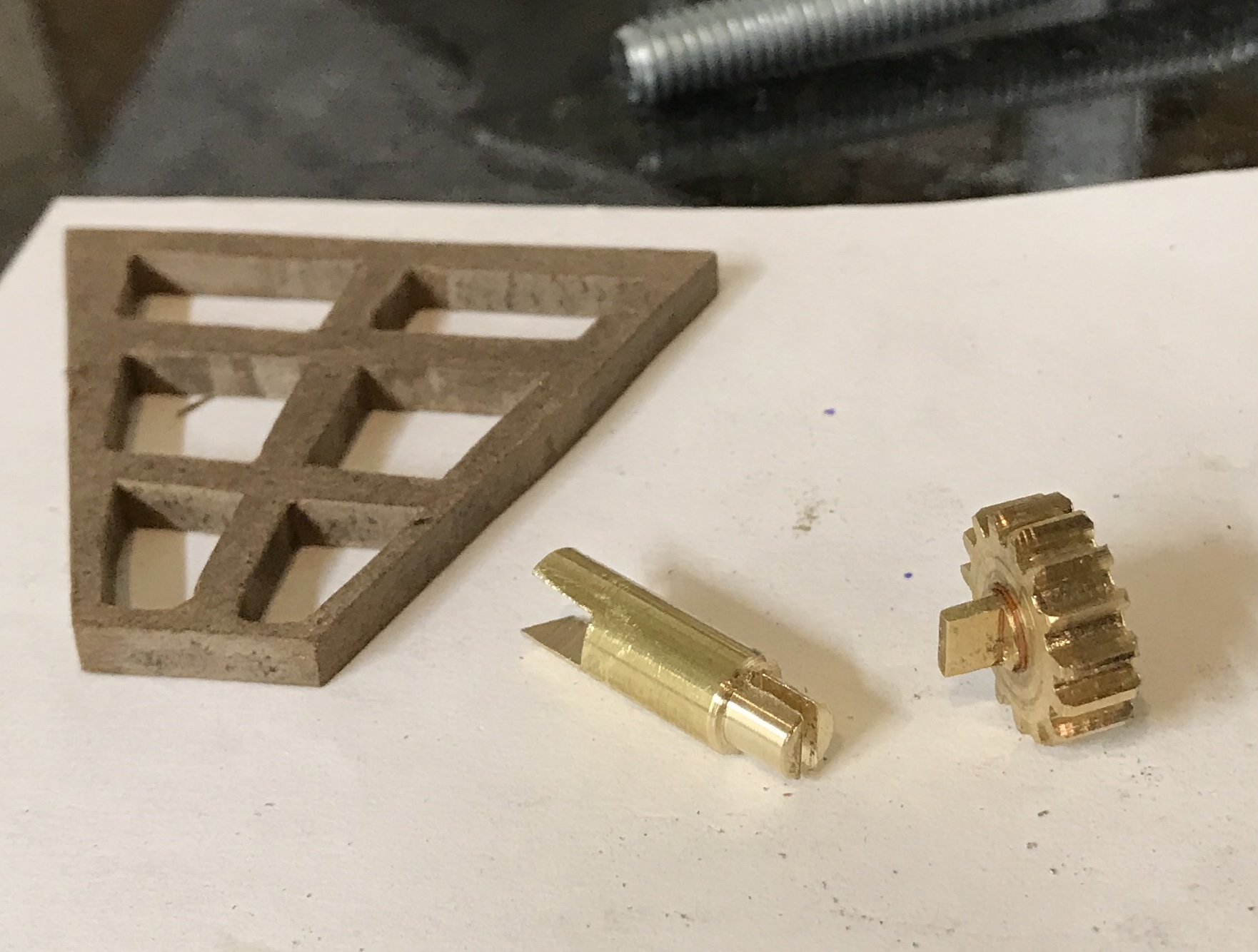
The trapezoid envisioned is a half size version of that on Wikipedia. It was sketched out on a scrap of 1/8" thick MDF. Holes were drilled in two inside corners for each of the six cutouts, windowpanes. These were cut out with the scroll saw. The sides of the windowpanes were cleaned up with needle files and then the window was lightly sanded with 220 grit paper.
A holder needs to be made to complete all of the parts. The holder needs to be long enough to support the middle of the window, while allowing the widest edge clearance. The slot to hold the window (0.150") will be cut at an angle to match the bottom of the window. The slot will be cut first followed by preparing the other end to fit over the axle's tab. The window holder will be held for slot milling in a small vee block.
A 1" length of 1/4" brass rod was faced on one end. The rod was held between a small vee block and a clamp from the finger plate in the milling vise. The angle was adjusted to match the angle of the long side of the trapezoidal window. After finding the side of the rod with the edge finder the table was moved to the center of the rod. A slot was cut in the end of the rod until the shallowest end was about 1/8" deep. (Cutting this way was challenging as the vee block kept shifting. A better way would have been using the angle plate.) The cut was then widened 0.012" on each side. This gave a tight fit on the window.
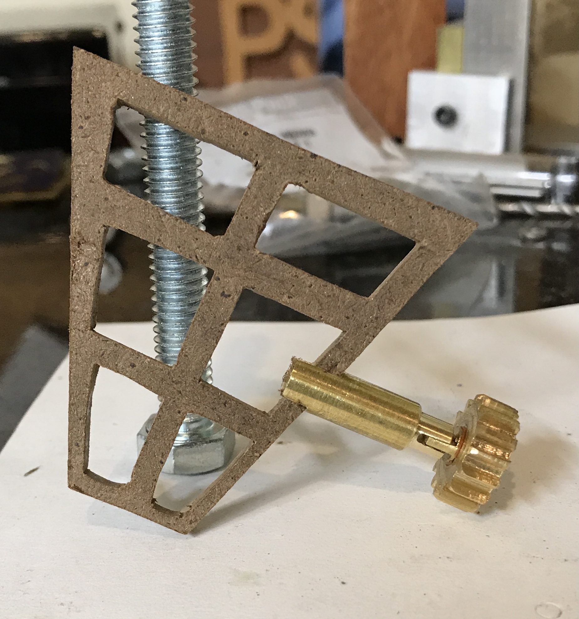
The slot was deburred and the opposite end was cut approximately to 3/4" with the hacksaw. After facing this cut end the rod was reduced to 0.188" to a sliding fit in the hole in the top plate. The rod was taken to the vise and the hacksaw was used cut a slot in the center of the reduced portion to the 3/16" depth of the reduced part. The slot was widened with a small flat file to fit the axle's tab. The photos below show the finished connector and the connector connecting the window and the axle.
All that remains at this point is drilling a hole for the handle to reach the worm. Then everything needs to be made pretty. Ideally, the window will be painted with different colors for the edges and the faces. The brass needs to be polished and some parts painted with varnish.
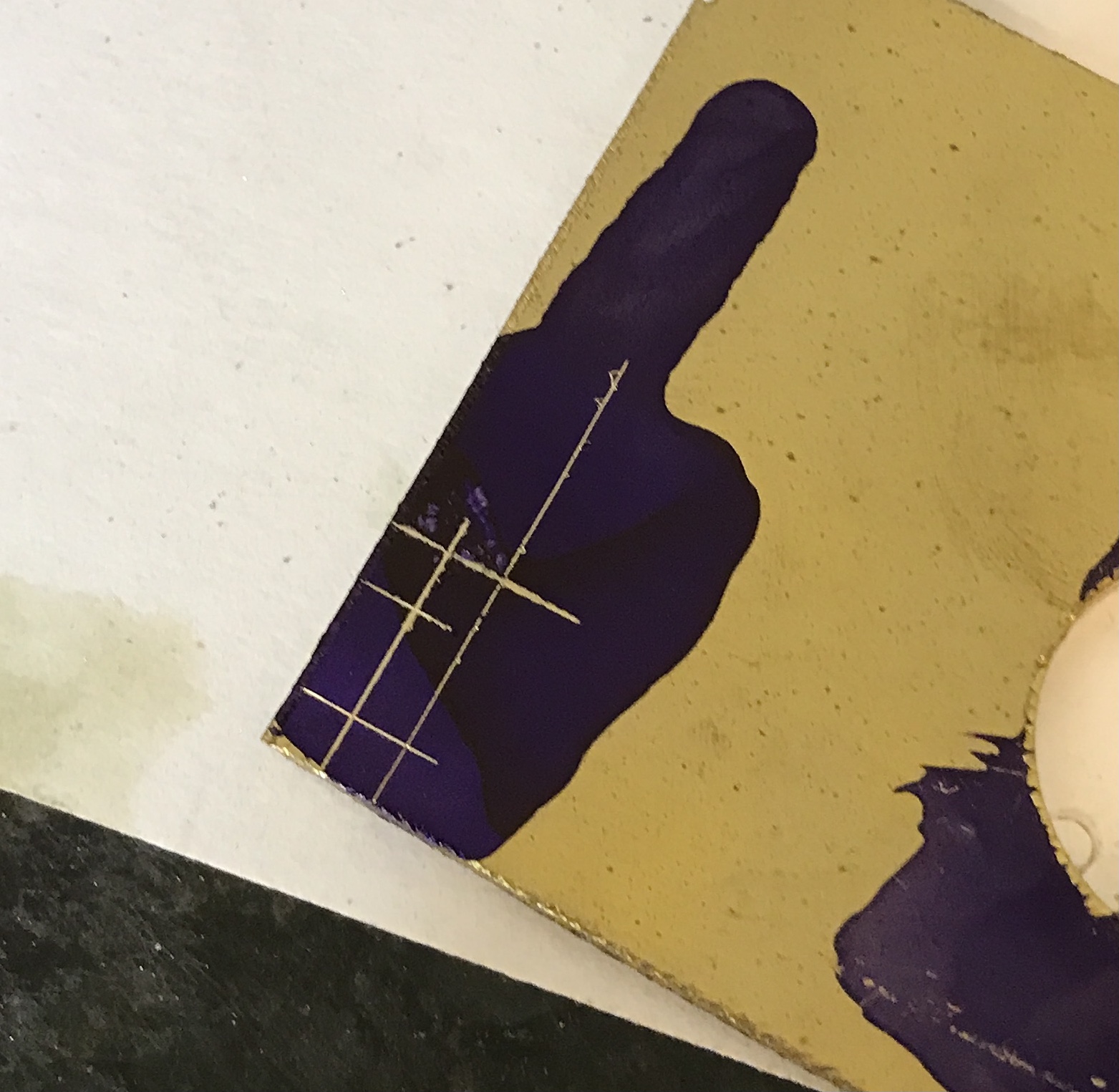
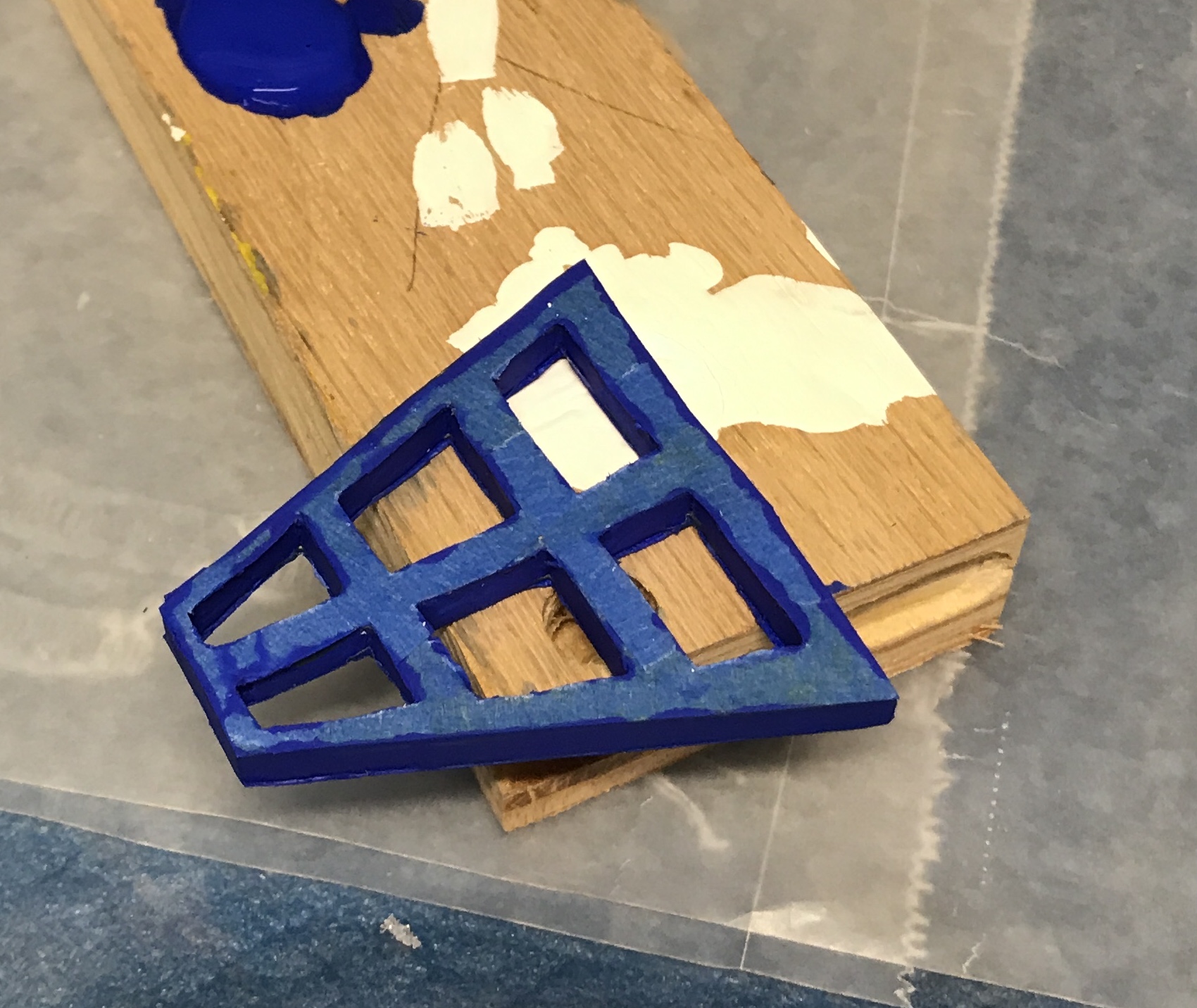
The window was painted with white acrylic paint. After this dried the faces were painted with two coats of yellow acrylic. After a further drying period the faces were taped with blue tape. The excess tape was carefully cut off including that in the openings. All edges were painted twice with blue acrylic paint. The taped and painted trapezoid is shown below. What a waste! Peeling the blue tape off took the yellow paint with it! The blue is not attached any better than the yellow.
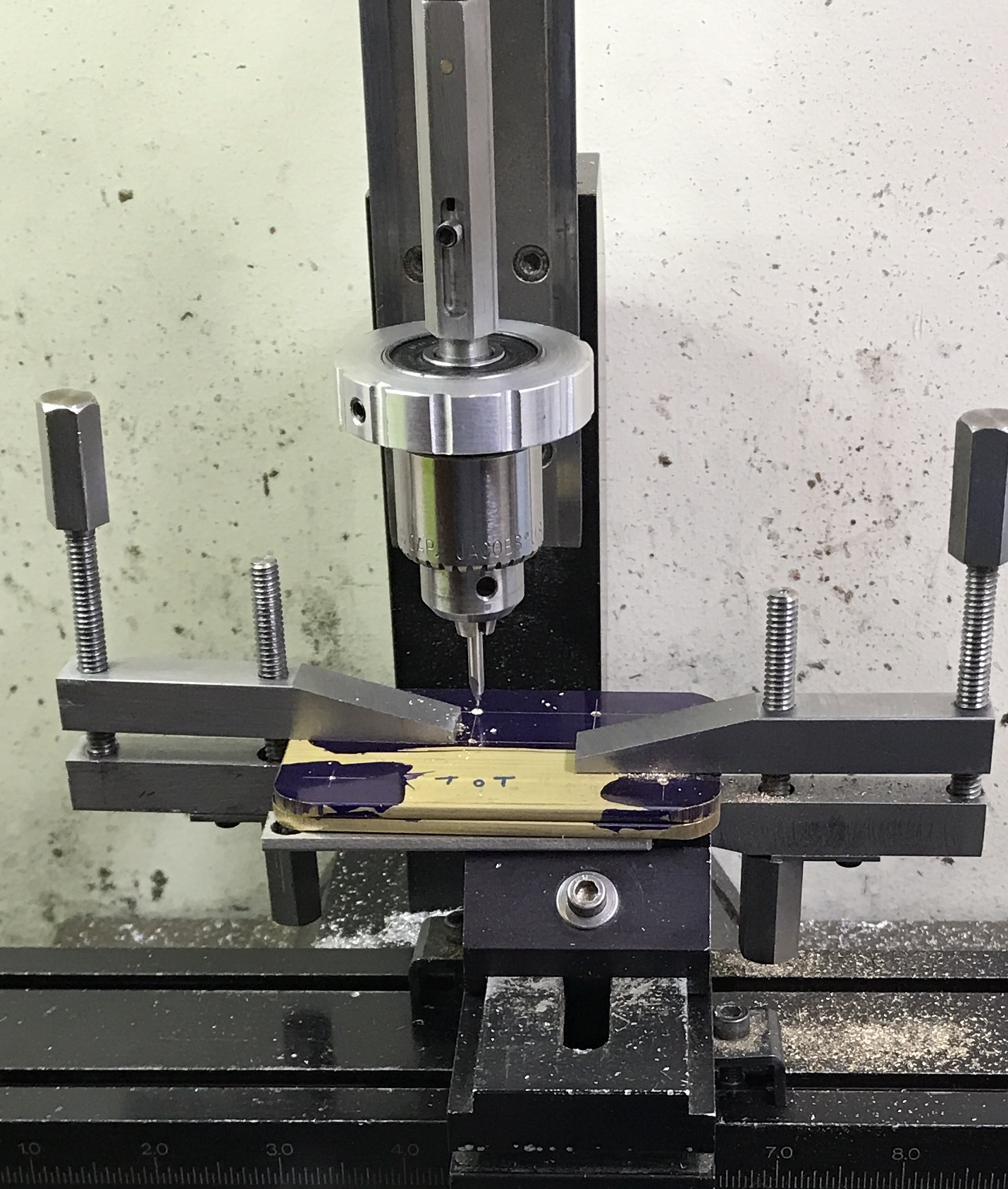
Drilling the hole in the Altoids box was simple. The box was marked for the hole after making a few measurements. From the bottom the hole height was set at 0.265" or the thickness of the box bottom, plus bottom plate, plus 1/8". The hole in the bearing was measured 0.75" from the back. A block of brass was clamped inside the the box. The box was held tight to an angle plate, the hole was started with a center drill and drilled through with a 0.189" drill. With the device assembled I discovered the handle connector to the worm was not long enough! It will have to be removed and replaced with a longer version. The photo below shows the setup for drilling.
The remaining yellow paint was removed from the trapezoid. Some of the blue paint was peeled off as well. The trapezoid was sanded with 220 grit paper. I found a can of silver paint. The trapezoid was spray painted with the silver paint. Two coats were applied. The photo below shows the silver trapezoid.
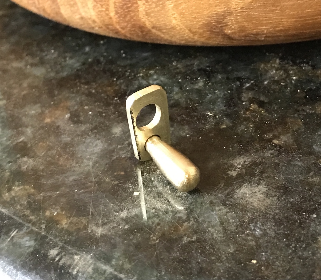
The mating pin in the handle was removed by tapping it with a punch, while holding the handle on the vise. A few gentle taps were enough to break the glue loose. A scrap of 3/16" brass rod was located. It had a faced end. It was held in the three jaw chuck with the faced end protruding. This was mounted as before on the square indexing block. The end was milled to the same screwdriver look as before. The part was then glued into the handle as seen in the photo below.
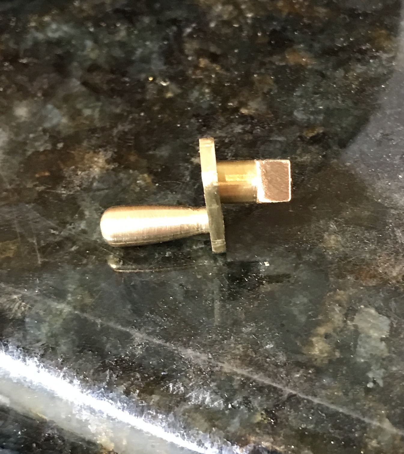
The mechanism was placed inside the Altoids box. The hole in the box does not align with the hole in the bearing! Vertical is okay, but the horizontal is more than 1/16" off. I believe I have another Altoids box. A second box was located (probably have six). It was drilled correctly and slightly larger than 3/16". The extension on the handle then came loose. So a third insert was made. This insert was 1" long, had a rest for the strap, and was glued and punched to hold it more tightly. This new insert is seen in the photo below.
Finally, it was cranked. I cannot see the illusion! A short movie of the spinning trapezoid is included below.